It’s Not Your Grandpa’s EGR System Anymore!
Share
Share

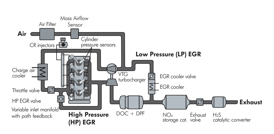
Let’s start with a little background on Volkswagen’s new EGR system. To meet the extremely tight Tier2 Bin5 standards for emissions (maximum of 10 milligrams/mile particulate matter and 70 milligrams/mile NOx for diesel vehicles) the new Volkswagen 2.0L CBEA TDI diesel engine uses a complex EGR system in conjunction with a diesel oxidation catalyst + diesel particulate filter (known as the DOC+DPF), a NOx storage catalyst and a H2S (sulfur) catalyst to achieve efficient NOx and particulate matter reduction.
The EGR system consists of two parts:
High Pressure Side – Exhaust gas is recirculated from the exhaust system after the Exhaust Manifold and controlled by a High Pressure EGR Valve. Exhaust gas is then fed into the Intake Manifold after the Throttle Valve.
Low Pressure Side – Exhaust gas is recirculated from the exhaust system between the DOC+DPF and the NOx storage catalyst. Exhaust gas is then fed through an EGR cooler and Cooler Flow Control Valve to the intake air system at the turbocharger compressor inlet. An Electronic Exhaust Throttle Valve is included between the NOx storage catalyst and the H2S catalyst. This valve is used to control differential pressure between the NOx storage catalyst and turbocharger and assists with Low Pressure EGR return flow and catalyst regeneration.
In addition, there are two EGR pressure sensors and four exhaust gas temperature sensors to measure the flow state, temperature and general health of the Exhaust After Treatment components.
Close monitoring of the EGR and Exhaust After Treatment components is critical for NOx reduction and proper regeneration of the DOC+DPR catalyst, the NOx storage catalyst and the H2S catalyst. A failure of any component will lead to excess emissions, and could potentially lead to failed catalyst regeneration cycles and eventual failure of the Exhaust After Treatment components.
WHEW! OK, so what does this all have to do with trouble codes P047A (DTC 001146) Exhaust Pressure Sensor 2 (G451) Open Circuit P047B (DTC 001147) Exhaust Pressure Sensor 2 (G451) Implausible Signal? The codes indicate a potential problem with the G451 Exhaust Pressure Sensor 2 signal (implausible) or wiring (open circuit). This sensor monitors the pressure and flow in the Low Pressure EGR system. The function of combined Low Pressure and High Pressure EGR system operation is continuously adjusted depending on engine operating conditions and RPM. No-load engine operation results in high amounts of High Pressure EGR application and low amounts of Low Pressure EGR application.
With rising engine load and engine RPM, the recirculation of exhaust gases is shifted to the Low Pressure EGR system to increase the recirculation flow rate. This allows for optimum NOx reduction at mid to high engine loads. At high engine loads, the cooled Low Pressure EGR system is much more efficient than the High Pressure EGR system at adding the correct amount of exhaust gas recirculation for NOx reduction.
The G451 Exhaust Pressure Sensor 2 monitors flow rate of the Low Pressure EGR system from after the diesel oxidation catalyst and the diesel particulate filter (DOC+DPR) to the EGR cooler assembly. The trouble codes indicate a problem with the G451 Exhaust Pressure Sensor 2 Signal or G451 wiring or connections.
To test the G451 Sensor:
Locate the G451 Exhaust Pressure Sensor 2 below a heat shield near the oil filler neck.
Inspect the exhaust pressure feed lines from the N213 EGR Valve 2 housing and from the base of the DOC+DPF assembly to the G451 Exhaust Pressure Sensor 2. The exhaust pressure feed lines must be intact, not leaking, not plugged or bent (Note: This is a critical step. Any leakage, restriction or damage to the pressure lines can cause the G451 to output an implausible signal.)
Inspect the G451 Exhaust Pressure Sensor 2 wiring as follows:
• Pin 1 (Black wire) = 5-volt power supply, ignition on, from pin T94/14 of the PCM.
• Pin 2 (Brown wire) = Good ground at all times from pin T94/79 of the PCM.
• Pin 3 (Green wire) = Signal return to pin T94/34 of the PCM. Values are about 0.48 volts with no exhaust pressure. The voltage will increase in a linear fashion as exhaust pressures increase.
Repair any wiring/connector defects as necessary.
If the G451 Exhaust Pressure Sensor 2 output voltage does not react as described and all of the wiring and pressure lines are OK, then the sensor is faulty and must be replaced.
In this particular case, the wiring to the G451 Exhaust Pressure Sensor was damaged. After repairing the harness normal G451 Exhaust Pressure Sensor operation was restored. The technology that is required to achieve mandated emission levels can seem overwhelming at first but with an understanding of how the system is designed to operate, the diagnostic process is not so far removed from Grandpa’s EGR!
Leave a Reply