

The brushless electronically commutated fuel pump is more efficient, produces lower emissions, and tends to last longer. No wonder it has found its way into the fuel tanks of the vehicles we’re now servicing!
By Jeff Taylor
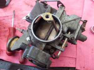
Even in the days of this carburetor, a steady supply of clean fuel at the correct pressure was required for proper engine operation.
A properly operating fuel pump is indispensable for smooth engine performance.
All internal combustion engines need the correct volume and quantity of fuel to be supplied to the engine – and it doesn’t matter if it’s an old downdraft carburetor, sequential fuel injection, or the latest gasoline direct injection (GDI) system.
If the fuel pump can’t deliver the needed volume and pressure of fuel, engine performance is going to suffer. Misfires, stumbles, lack of power, and even a no-start condition can result.
But proper fuel delivery consumes energy. And with the tight constraints on fuel economy and emissions, even the fuel pump is under the gun to do the same work it always did… but with less energy.
The fuel pump is the heart of the vehicle’s fuel system. Yes, many vehicles now have a high- and low-side fuel pump with their GDI system, but the electrical, low-pressure fuel pump (typically located in the tank) has been the focal point of the latest developments. The GDI system needs to have a transfer (or low-pressure) fuel pump to supply the high-pressure pump the fuel it needs for proper engine operation.
The familiar electric fuel pump

The traditional DC commutator-style (brushed) fuel pump that we’re familiar with uses a tubular outer steel shell with a fuel inlet/pump assembly at one end, and the pressurized outlet/electrical connection on the other end. Dissect it and you will find several components inside: an armature, a stator, a commutator, brushes, and the pump assembly. These are the major components, but there could be other parts, depending on the design, usage, and the manufacturer’s individual preferences.
All DC motors rely on continuously opposing magnetic fields and the forces they create to cause a rotation. It’s this rotational force that is harnessed to perform work.
The common brushed fuel pump will use fixed permanent magnets as the stator. These are commonly attached to the inside of the outer shell. These magnetic arc segments – commonly made of an inexpensive but brittle ceramic ferrite material – will be custom ground to the exact curvature and shape required by the manufacturer to closely hug the armature without touching it.
The space between the stator and the armature is very important. The closer they are (without touching), the stronger the forces of repulsion will be.

The armature assembly is in the centre of these magnetic arcs and is the rotating part of the motor. It’s attached to the fuel pump assembly on one end and supported by bearings or bushings to allow rotation while limiting friction.
The armature will have a commutator to provide current from the brushes (more on those brushes in a moment) to the windings or coils to create a magnetic field. The armature uses specially designed laminated steel plates to enhance the magnetic field created by the windings when current is applied to them.
When current is applied to the armature winding, it will create a magnetic field that will be repelled by the magnetic fields of the fixed magnets of the stator. But this repulsive force is only strong for a short distance, so more than one armature winding is used to multiply the repulsive force and make the motor rotate smoothly. Typically six windings are used.
Turning the individual windings on and off at the correct time to provide the magnetic fields needed for rotation is the job of the commutator and brushes. To perform this task, the commutator and brushes act as a rotary switch.
A set of graphited carbon brushes are used to transfer the current to the rotating armature’s high-copper-bearing alloy of brass commutator segments. If the fuel pump is being used in E85 fuels, then the commutator will be made of carbon-surfaced material to extend wear in the more corrosive fuel. As the brushes make electrical contact with the commutator segments, current flows through the windings and a magnetic field is produced.
It’s this magnetic field that’s pushed away from the fixed magnetic fields of the arc segments glued to the shell. This force starts (and maintains) the rotation because as that winding reaches maximum force, it’s shut off and the magnetic field collapses. But just as this happens, the commutator will have moved, allowing the brushes to connect to the next segment and its windings, creating a new magnetic field.

The armature is attached to the pump, which can be of several types. The gerotor is the most common, but plastic turbine and fan blades have also been used. Engineers are always looking for high-efficiency alternatives with low noise and lower cost.
This very common brushed style of fuel pump motor has several advantages and disadvantages. The key advantage is that it’s simple and relatively inexpensive to manufacture. Unfortunately, that simplicity and cheapness can lead to some shortcomings.
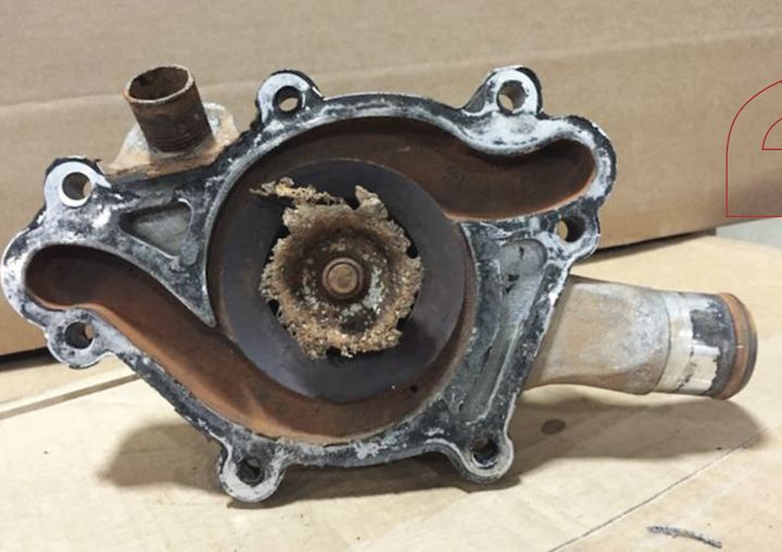
The commutator tends to be a major issue in fuel pump failures. Because most fuel pumps run wet, the gasoline acts as a coolant for the armature and a lubricant for the brushes and commutator. But the gasoline isn’t always clean. Fine grit and debris in the gasoline and fuel tank can get by the in-tank filter. This grit wreaks havoc on the brush and commutator surfaces and accelerates wear.
Most fuel pump manufacturers will tell you that commutator surface wear and damaged brushes are a leading cause of fuel pump failure. Constant low fuel tank levels can cause a fuel pump to overheat, and overheating is another frequent cause of fuel pump failure.
Electrical and mechanical noise is also an issue. Electrical noise is generated by the arcing and sparking that occurs as the brushes make and break contact on the commutator. As a prevention, most fuel pumps will have both capacitors and ferrite beads at the power input to limit radio frequency (RF) noise. Mechanical noises from the impeller, pump gears, and bearing assemblies, or cavitation from low fuel levels will all be augmented because the fuel tank will act like a big speaker and amplify even the smallest sound.
The brushed style fuel pump is generally inefficient. Commutator motors are only about 75-80% efficient. The ferrite magnets are not that strong, which limits their repelling force. And the brushes pushing on the commutator create energy, which ultimately robs friction.
Those concerns, and the fact that manufacturers are increasingly concerned about fuel economy and emissions has led fuel pump technology to evolve. It is being altered to reduce emissions and lighten the load that a fuel pump puts on the electrical system.
A more efficient design

Fuel pumps draw current from the engine-driven alternator. A fuel pump needs full voltage to operate at full speed. A turbine fuel pump will typically operate at 7,000 RPM or higher, but it’s depending on at least 13.5 volts to do that.
But the fuel pump rarely needs full speed and because a fuel pump’s efficiency is directly related to its speed. Cutting the pump’s speed increases efficiency. Pulse width modulation (PWM) in the fuel pump voltage allows the PCM to control fuel pump output, controlling its speed to closely match the needs of the engine.
Under low-load situations, pump output can be as low as 10 to 20%, depending on pump design. This not only improves efficiency but prolongs the life of the fuel pump.
The move to a brushless electronically commutated (EC) fuel pump motor design has several advantages and increases pump efficiency. The brushless EC motor design is 85 to 90% efficient and some manufacturers claim a 36% drop in power consumption.
A brushless EC motor in its simplest terms is a brushed motor built inside out. The permanent magnet parts of the motor are located on the armature, and windings are now attached to the outer case. This not only eliminates the need for brushes and the commutator, but it dramatically reduces pump wear and friction from brush drag. Brushless EC fuel pumps reduce RF noises because there’s no arcing from brush commutator contact.
Using rare earth (Neodymium) magnets that have a higher magnetic density than the ferrite arc magnets creates more power from a smaller lighter motor. It also means that the armature doesn’t need to be cooled. The windings are now able to be cooled by the outer case’s larger surface area.
A brushless fuel pump’s output flow, speed, and pressure can be closely matched to meet the engine’s demands, lowering fuel recirculation in the tank, and keeping the fuel temperature lower – all of which results in lower evaporative emissions.
There are drawbacks to the brushless fuel pump though, and one of them involves the electronics needed to control, operate, and start the motor. Because the electromagnetic coils now surround the permanent magnet armature, they need to be switched on and off, just like the old commutator did. To accomplish this the use of semiconductors, complex electronics, logic circuits, field-effect transistors, and Hall effect sensors will control what coil is turned on and when, to force the rotation.
And, of course, the major drawback to the brushless EC motor is that they are more expensive to produce.
The future of brushless performance

The brushless EC fuel pump’s efficiency is one reason that these pumps have found their way into the fuel tanks of the vehicles we’re now servicing. They also produce lower emissions. And as a bonus, they tend to last longer.
Fuel pump manufacturers are claiming a brushless fuel pump life of about 10,000 hours of operation. And that could increase to as much as 20,000 hours in the future.
This amount of durability has engineers looking at considering a non-serviceable fuel pump strategy (some hybrids have adopted this technology already). Eliminating the need for a separate tank opening just to allow fuel pump service improves a vehicle’s evaporative emissions performance. And this is something that an inexpensive brushed fuel pump’s dependability just can’t provide.
 Jeff Taylor is lead technician at Eccles Auto Service in Dundas, Ont.


Leave a Reply