

Countertalk For the Counterperson: Starting and Charging System Basics
Share
View the latest digital editions of all of our publications or head straight to the archives
Share
While there are many cases of curious problems resulting from the increasingly complex interactions of various electronic systems under the hood and even though the Cadillac alternator illustrated did inaugurate the age of the liquid cooled alternator, the general principles of a starting and charging system on today’s cars is probably the least changed of the systems located under the hood.
The Starting System Circuit is made up of the starter motor and solenoid assembly–whether integrated or separate– the battery, the starter or ignition switch, and the wiring that connects it all.
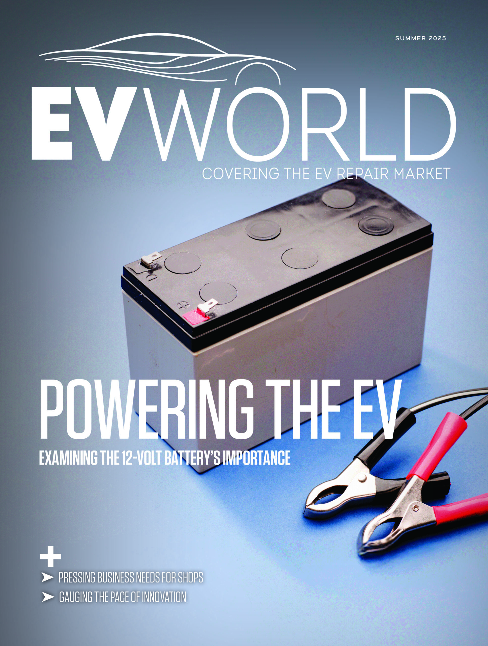
The lead-acid Battery is the keystone component of the starting system and until 42-volt systems bow in, each automotive battery will continue to be made up of six cells generating 2.1 volts each. Bathed in an acid bath, they are linked in series to provide the customary 12.6 volts. Some spiral-wound batteries use a different construction, but the number of cells remains the same. In conventional construction, the number of plates in each of these cells helps determine the total amps that the battery can provide at this voltage; the more plates, the more amps. As these become damaged, the ability for the battery to provide its rated CCA diminishes, although it may still maintain 12.6 volts. It is also helpful to remember that temperature drops can dramatically reduce the amperage a battery can deliver to the starter.
The Starter is an electric motor that provides the rotation to the engine on start-up. As electric current passes through its coil windings, it causes starter to rotate.
The Starter Drive consists of that drive assembly and the solenoid. There are three basic types: direct drive, solenoid activated; reduction gear solenoid activated; and positive engagement, relay activated.
On the first two, the Solenoid which usually sits atop the starter, controls the engagement of the pinion gear with the flywheel gear. It also closes the heavy-duty contact that provides the high current to the starter motor. Both occur when the ignition/starter switch is turned to the start position.
The Solenoid is an electromagnetic plunger assembly that, when energized, pulls inward forcing a lever to extend the drive assembly until it meshes with the flywheel. On the reduction gear type, the rotational speed of the starter is stepped down to increase torque for larger engines. A positive engagement, relay actuated system is similar to the direct drive, solenoid activated assembly except that it uses the strong magnetic field generated by the motor’s field coil to pull the plunger lever.
Once started, the Overrunning Clutch allows for the quick disengagement of the pinion gear from the flywheel to prevent damage to the starter from the high engine rotational speeds. A Bendix Drive system is an additional design for this purpose which uses a set of gears on the armature shaft and on the inner surface of the pinion gear. Both systems cause the pinion to be retracted when the engine rotational speed exceeds that of the starter.
Some starter circuits employ a Ballast Resistor bypass circuit. A ballast resistor or resistance wire in series with the ignition coil’s primary circuit is used in older systems to protect it from excessive current but, because the ignition circuit requires full current during starting, either a separate, secondary circuit is employed or a separate set of contacts in the solenoid.
Starting an engine is an energy intensive affair. Enter the Charging System.
The Charging System has five main components: the alternator, the regulator, the pulley and belt drive system, the fusible link and a dash warning light or gauge.
An Alternator’s job is to generate electricity. This used to fall to a Generator years ago but an alternator is a more efficient “generator” of electricity. Generators provided DC current to the battery. An Alternator actually produces AC current. Since this is of no use to the battery, a DC electrical device, this current must be converted in DC current.
The Rectifier or Diode does just that. Diodes only allow electrical current to flow in one direction and prevent the battery from discharging to ground through them and the alternator’s windings. Diodes may be packed singly or combined in a single package and can be mounted on or in the alternator. As alternator rotational speed rises, its rapidly cycling positive and negative electrical pulses (alternating current) is converted into a near continuos, steady DC current. As the alternator’s rotational speed increases, so does the voltage it generates.
The Regulator controls this voltage, preventing it from rising to the point where it can damage electrical components, including the alternator itself. A Regulator works by turning on and off the voltage applied to the rotor through the brushes and slip rings as it rotates. Restricting this current controls the current flow induced in the stator windings. This on/off switching takes place many times per second. The regulator may be internal to the alternator or mounted externally. A malfunctioning regulator can have all sorts of strange effects on other systems.
The Fusible Link is a safety device designed to protect the voltage regulator, diodes and alternator from short circuits.
Gauges and Lights keep the driver informed, to some extent, of the functioning of the charging system. An ALT warning lights will let the driver know of an alternator malfunction, an Ammeter will read the amount of amperes being received by the battery and a voltage gauge will register the voltage being generated by the alternator.
One of the classic problems which occurs with the starting and charging system is the “battery or alternator” question. While alternators may appear to be operating well under some test conditions, they may become erratic after extended driving in hot conditions, for example. Additionally, if the belt tension on the pulley is insufficient, poor charging may result.
For counterpeople, it is important to remember that the alternator is not a battery charger. Installing a new one without ensuring that the battery is in good working order is just asking for trouble.


Leave a Reply