

Diagnostic Tips for Chrysler’s LIN-Bus Network
Share
View the latest digital editions of all of our publications or head straight to the archives
Share
There is a new vehicle communication network in the Chrysler world: Local Interconnect Network (LIN). LIN-Bus is a small, relatively slow and inexpensive network compared to the Controller Area Network (CAN-Bus). LIN is used mostly for body electrical systems.
There are several benefits to using LIN-Bus. It is very reliable, reduces vehicle build costs, and uses less wiring compared to other communication systems. It is also extremely easy to diagnose using a compatible scan tool and a Digital Volt-Ohm Meter (DVOM).
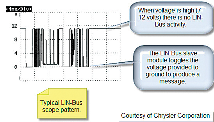
The LIN network is made up of one master node (module) and several (up to16) slave nodes. Since the master module is connected to the CAN-Bus, all scan tool diagnostics are done via the master. There is no way to communicate directly with the slave nodes. The operation of LIN-Bus is simple. The LIN master sends out a reference voltage (7 to 12 volts) to the LIN slave. The slave has an internal processor that pulls the voltage low to produce the LIN-Bus message. Figure 1 shows a typical LIN-Bus lab scope pattern.
The most common systems in Chrysler vehicles that use the LIN-Bus network are turn signals, wipers, radio controls, heated seats, power windows, power locks, power mirrors and the Tire Pressure Monitoring System (TPMS). This article will cover three examples of how the LIN-Bus works and tips for proper diagnosis.
Example 1: Let’s first look at the turn signals on a 2008 RT body. This body style is found on the Dodge Caravan and Chrysler Town & Country. Figure 2 shows a simplified diagram for the turn signal system on this vehicle.
The LIN master for this system is the Cabin Compartment Node (CCN), also known as the instrument cluster. The LIN slave is the multi function switch. When the turn signal switch is positioned for a left or right signal a LIN-Bus message is transmitted to the CCN on the dedicated LIN wire. The CCN then sends a CAN/IHS-Bus message to the Totally Integrated Power Module (TIPM) and the TIPM flashes the turn signal bulbs on the exterior of the vehicle. If this vehicle comes into your shop with the turn signals inoperative, diagnosis is very easy. Connect your scan tool and go to the CCN data stream. Look for the turn signal switch bussed input. When you switch the lever for a turn, the data should reflect that. If the input does not change then check the power, ground, and LIN wiring to the multi-function switch.
An easy way to check the LIN wiring is to unplug the slave module and check the ‘at rest’ voltage of the LIN wire. The master should send out the 7 to 12 volt reference. If the wiring to the multi-function switch checks out good, replace the switch. If the input shows to be correct, check the bussed outputs. The CCN should be bussing a message to the TIPM on the CAN/IHS-Bus. The bussed output should show that a left or right turn signal is desired. If not, check the powers and grounds at the CCN and replace if necessary. If the inputs and outputs are correct in the CCN data stream, check the TIPM data. Look at the bussed inputs. If they show that the left or right turn is being inputted to the TIPM, then the TIPM is recognizing the message from the CCN and it should be flashing the bulbs. Make sure the wiring from the TIPM to the bulbs and the bulb grounds are good. Replace the TIPM if all the wiring is intact.
Example 2: Now let’s talk about the TPMS on a LX body found on the Chrysler 300, Dodge Magnum, and the Dodge Charger. The premium system has the ability to determine the specific tire pressure of each tire by using a tire pressure sensor/transmitter with a unique transmitter ID in each wheel, three trigger modules attached behind the splash shield near the left front, right front, and the left rear wheel, and the Wireless Control Module (WCM).
The WCM is also used for the immobilizer system and the Remote Keyless Entry (RKE) receiver. Each trigger module is connected to the WCM via the LIN-Bus. When the vehicle is driven, all four sensor/transmitters periodically send out signals. To determine each tire position, the WCM sends a LIN-Bus message to one of the trigger modules. The trigger module then produces a 125-kilohertz (kHz) signal that commands the pressure sensor to produce a constant signal. The WCM then determines which transmitter ID responded and tags it to a specific corner of the vehicle. This process repeats to the two remaining trigger modules. Once the WCM identifies and tags which of the three transmitter IDs respond, the fourth tire position can be determined. Remember that there is no scan tool communication with the LIN slave modules, which in this case are the trigger modules. All fault codes and data are retrieved in the master module, the WCM.
Example 3: A PT Cruiser comes into your shop with the airbag light on. Scanning the airbag module reveals a B1C2F (Passenger Airbag Indicator Status Mismatch). Step 1 of the flow chart for this trouble code is to check for codes in the Instrument Panel Cluster (IPC) and diagnose all IPC codes. Upon scanning the IPC, a code U113B (Lost Communication with Switch Bank Module) was set. The switch bank module is connected to the IPC via the LIN-Bus and also houses the passenger airbag indicator bulb. Now things are starting to make sense.
Following the flow chart for the U113B code is only three steps:
1) Check the power supply to the switch bank.
2) Check the ground to the switch bank.
3) Check the LIN-Bus circuit between the IPC and the switch bank.
If all check out OK, the vehicle needs a new switch bank module. When you change the switch bank module you are also changing the passenger airbag status bulb, which will likely repair the airbag trouble code. This is a really good example of how different systems can be tied together.
As you can see, having the proper diagnostic equipment is necessary to accurately diagnose these systems, but using compatible tools makes the diagnosis fairly easy and straightforward.
Help! 2009 DODGE Avenger with one code “U113B” and NOT experiencing any of the problems discussed here. However, The Problems are; (Key on) “NO Fuse” in Odometer area of Tachometer Right most dash gauge (All working fine except FOB). (Key off) NO Interior lights, illuminate switches only, NO door locks, NO electric windows, NO Tunk Release, NO Emergency flashers, Radio won’t turn off upon door opening, FOB only makes Head Lights and tail Lights flash when door unlock button is pushed and Panic button works. Replaced TIPM Replaced the in Dash Instrument Message area (left most Gauge) Now the Outside Temperature works! Sent out the Speedo for matching Rebuild Nothing, no improvement 🙁 New Red Top Battery, New Battery Cables, Grounded all grounds on Driver’s side strut tower to the Battery negative with large Battery cable also on Driver’s side strut tower. Runs and starts better! Any ideas?
Are you able to check the ground to the switch bank module? Do a voltage drop test with ignition on (so use a multimeter, red lead to the earth at the switch bank module and black to a chassis earth). If you get a voltage above about 0.3v then you’ve got a bad earth connection.
The fact that you get better running with an earth connected between chassis and battery suggests it may be a bad earth somewhere.
Check all the chassis earths, make sure they’re tight and have a good clean connection. Check any straps between the engine and chassis in particular.
Also check a wiring diagram- find out where the module earths and check there!


Leave a Reply